
Abstract: As proposed in 1979 1 , standing waves of polychromatic laser light can trap atoms, molecules or larger particles to provide a free-standing reflective optical surface. Such mirrors must be fabricated in space and may in principle reach sizes beyond 10m, using techniques related to optical tweezers and atom traps. Laboratory testing in vacuum tanks is becoming possible. Diode lasers having adequate tunability, lifetime and energetic efficiency became available. Possible designs are discussed.
1. Introduction
While Earth-based mirrors generally have a rigid substrate carrying a thin reflective film, it does not have to be so in space: a pair of laser beams can replace the rigid substrate for maintaining the film . During the two decades elapsed since the idea was considered , appreciable progress occurred in the art of trapping atoms and particles, as illustrated by the Nobel prize recently awarded to S.Chu, C. Cohen -Tannoudji and B.Phillips . Highly efficient lasers became available, in the form of diode lasers emitting adequate levels of power .
The success of the Hubble Space Telescope is now triggering a race towards much larger mirrrors in space. The fact that an umbrella is judged necessary to shade the unenclosed mirror of the NGST , so that it be passively cooled to low temperatures, makes it look quite similar to the " pellicle" telescope design initially considered . The time has come for practical testing in vacuum tanks .
2. Principle of the pellicle mirror
In gravity-free space, a flat optical beam splitter, assumed to have 50% transmission and reflection, tends to become trapped by radiation pressure if illuminated by a pair of coherent wavefronts incident on both sides symetrically ( figure 1) . Indeed, the beam-splitting film is then parallel to the standing waves created by the interference of both waves . Translating the beam splitter changes the phase difference between the pair of waves emerging on one side , so that the outcome can be destructive on one side and constructive on the other side, owing to energy conservation since the splitting film is assumed absorbtion free.
Radiation pressure thus pushes the beam splitter towards the side of destructive interference. If allowed to translate freely, in response to this force, the beam splitter soon reaches a region where the radiation pressure changes direction , as does the emerging beam. It thus tends to become trapped at an intermediate location. There is a set of such stable positions at regular spacings , the periodicity of which is [lambda]/2 if both incident beams are propagating in exactly opposite directions .
Trapping the beam-splitter on a specified standing wave requires that this particular location be first designated , and this is achievable in polychromatic light by making it a nodal surface for all the wavelengths used. Equalizing both optical paths from the laser to the designated surface provides a contrasted central fringe at this surface. If the laser is now operated in a single-wavelength mode , but with a tunable wavelength setting, shifting the setting from red to blue will shrink the standing wave pattern on both sides of the central fringe. This will therefore move the beam splitter towards the central fringe. Repeatedly shifting the laser wavelength, according to a saw tooth schedule as shown in figure 4 , tends to bring the beam splitter to the central fringe.
The principle can possibly be applied to various materials capable of behaving like a beam-splitting film, as discussed below , and no substrate is required if the material has a stable behaviour in unsupported thin film form.
For a large astronomical mirror in space, one typically needs a paraboloïdal or nearly paraboloïdal shape such as used in the Ritchey-Chrétien configuration of the Hubble Space Telescope. A pair of coherent point sources of light naturally produce standing wave sheets having hyperboloïdal shapes. Modifying the shape of one sheet, selected to serve as the central fringe where the mirror will be trapped, to make it paraboloidal ( or nearly so) is generally achievable with a correcting lens or mirror acting on one of the emitted beams , and which can be much smaller than the desired telescope mirror . A typical arrangement considered ( figure 2) has a tunable laser suitably located to generate a central interference fringe having the desired curvature . A pair of small mirrors carrying adequate aspheric deformations provide the exact paraboloidal shape required for the central fringe where the mirror is to be trapped. The primary focus of the telescope is located some distance towards the star, and can be equipped with instruments , unless a Cassegrainian secondary mirror becomes preferred.
The delicate pellicle , typically 100 nm to possibly a few microns thick, obviously has to be fabricated in space rather than flown, in folded form, from Earth. Several ways of doing it , with metal atoms emitted from an oven or a smoke of prefabricated particles, are considered.
Once the particles have been trapped at the paraboloïd locus, the trap has to be maintained, either continuously or intermittently . Intermittent laser illumination, for example using millisecond pulses repeating at second intervals, may prove preferable , together with detector gating, for avoiding any contamination of stray laser light in the astronomical image.
The delicate mirror structure must be protected from direct sunlight, the radiation pressure of which is equivalent to 1 kW/m2 of laser light. Umbrella strurctures such as considered for the NGST are of interest in this respect. For very large mirrors, the use of a small asteroid as an umbrella may be envisaged, in which case the pellicle telescope should possbbly be mechanically attached to the asteroid.
3. Mirror material: atoms, molecules or particles ?
Metal atoms in vapor form tend to have a limited number of narrow absorbtion lines , and this can affect the effectiveness of the laser tuning schedule , but recent results ( Salomon 1999, private communication ) indicate that this is nevertheless feasible. It may thus prove possible to attract such atoms towards the central fringe and condensate them into a solid, free-standing metal pellicle. Persistent trapping would then require that the pellicle be partially transparent at the laser wavelengths , which may differ from the astronomical wavelength band of interest, where full reflectivity is desirable . However, current techniques of atom trapping deal with highly diluted atom clouds , which would require impractically large condensation times.
Instead, prefabricated particles having a suitable optical behaviour may be released, in the form of a smoke-like cloud, in the region where they can be driven by the laser field towards the central fringe. Dielectric spheres smaller than the wavelength appear to have adequate properties since their forward and backscatter intensities have been shown to be equal (Maystre 1999, private communication ) . If the backscatter intensity can be further increased at the astronomical wavelengths , then a mirror with reflective efficiency higher than 50% can be expected. This may be achievable in the infra-red with gold-coated glass spheres, if the laser has a visible spectrum.
The recent advances in the area of photonic crystals may lead to dielectric optical structures having the desired properties of full reflectivity in the astronomical band and 50% reflectivity in the laser band. Recent findings at MIT give hints of multi-layer dielectric mirrors with high reflectance in a wide range of wavelengths and incidence angles. Particles with internal structures of this sort may be of interest .
Trapping experiments 2 carried out in water with spherical polystyrene particles have evidenced a lateral force, caused by the optical interaction of the particles, which tends to space them laterally at multiples of the wavelength. A single sheet with a square or hexagonal array of particles spaced by one wavelength can be expected to have favorable chracteristics if used as a mirror. More elaborate particle strutures, with different shapes such as needles or platelets, or multilayer structures, may also be considered. Amorphous or crystal particle structures may have different performance. Macromolecular structures are equally of interest.
In the absence of damping action such as caused by water in the experiments just mentioned, the stability of a trapped sheet in vacuum has to be ensured otherwise. Passive cooling in the shadow of the umbrella tends to lower the temperature down to 30deg.K.
The pellicle behaviour at the mirror's edge must also be investigated . Whether a continuous leakage, requiring refills, can be prevented is unclear . Techniques for preventing leakage should be explored.
Diode lasers are of interest for their energetic efficiency and their broad tunability. New materials such as GaN are expected to cover the violet to yellow range. A "centipede" diode laser structure providing an electrically tunable spectrum has been described 6, and mulitiplexed arrays
of single wavelength power diodes can also be used.
4. Limiting size for mirrors
The main factor limiting the mirror size is likely to be the power of the trapping laser. The low temperature probably allows a reduced power for maintaining the mirror trap. However, the accelerations needed when re-pointing the telescope may require temporarily increased laser power during these maneuvers. The preliminary calculations 1 had indicated that a 10m mirror trapped by a 10-Watt laser can stand angular accelerations of 2 microradians. s-2, taking 30 minutes to repoint the telescope through 90deg.. If however the umbrella is fully covered with photovoltaics, much more power is available to the laser . In such conditions, the maximal angular acceleration of the mirror is given by :

where c is the velocity of light , P0 is the solar power per square unit , [eta] is the combined efficiency of the solar cells and laser, u is the volumic mass of the pellicle, [epsilon] its thickness and D its diameter . For P0= 1,000 W.m-2 ; [eta] = 10% ; u = 1,000 kg.m-3 ; [epsilon] = 100 nm and D = 100m , the repointing time through an angle [theta]r = 90deg. is about 2 minutes. It becomes half a minute if the mirror size is 10m .
It should be noted that the umbrella's own acceleration in the anti-solar direction, caused by
solar radiation pressure, would exceed the trapping capability of the laser beams if the mirror and umbrella had the same areal mass. But the mirror is typically much thinner than the umbrella and no such problem arises.
The limiting size can be considerably extended if the mirror is made of relatively small segments, in the form of a large interferometric array having a higjhly diluted aperture. Recent work4,5 has shown that such arrays, which may ultimately span thousands of kilometers and combine hundreds of sub-apertures, can provide direct images using the so-called "densified pupil" imaging mode. Using a single laser, as shown in figure 6, to trap the mirror elements achieves their correct phasing. Free flyers are needed in this case to carry the optical elements and the separate umbrellas needed to shade each element of the trapped mirror. The repointing of the giant telescope thus implemented is longer than indicated by the previous equations. No repointing is however needed in the case of the "moth-eye" design4 , where mobile focal stations provide full-sky coverage.
6. Conclusions
More theoretical work is needed on the various techniques usable for trapping reflective matter in standing waves of laser light. Earth gravity being negligible for sub-wavelength particles when laser power exceeds 10 W/m2, such methods can now be subjected to laboratory testing in vacuum cells.
It is too soon to predict the size of the mirrors which may become achievable in space with such methods. The limits can possibly be overcome to create diluted interferometric mirrors , with a single laser illuminating a diluted array of mirror elements. These techniques can in principle solve the problem of achieving and maintaining diffraction-limited surface accuracy on large mirrors.
References:
1. "Standing waves and pellicle: a possible approach to very large space telescopes", Labeyrie,A. Astron. Astrophys., 77, ppL1-L2, 1979.
2. Burns, Fournier, Golovchenko, Science, 149, 1990.
3. Van Bladel , "Electromagnetic fields", McGraw-Hill, p.282
4. "Direct searches: imaging, dark speckle , coronagraphy", Labeyrie,A. 1998, NATO Advanced Study Institute, in "Planets outside of the solar system", 5-15 May Cargèse Corse.
5. Riaud,P. Boccaletti,A., Moutou,C. & Labeyrie, A. , submitted A&A, 1999.
6. "Optical data storage in microfibers" , Labeyrie, A., Huignard, J.P. & Loiseaux,B.
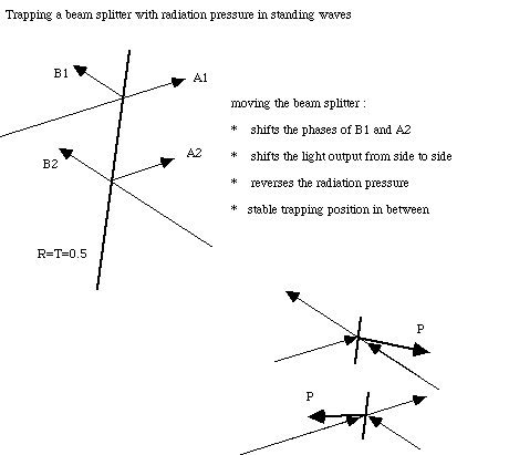
Figure 1: trapping a beam splitter with radiation pressure in standing waves produced by two coherent beams .
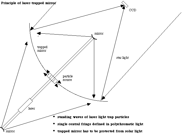
Figure 2: Principle of space telescope having a laser-trapped mirror . A laser and two small mirrors produce a pair of diverging beams propagating in opposite directions. Their interference pattern has standing waves where particles can be trapped by radiation pressure, thereby genrerating a Bragg hologram or a mirror which can reflect starlight to a focus .
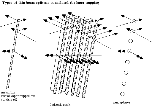
Figure 3: Various mirror structures which may be obtainable by trapping atoms or particles in standing waves
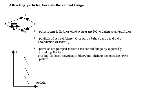
Figure 4: laser tuning schedule for defining a central fringe where the particles become attracted. The blueward wavelength variation shrinks the trap symetrically on each side of the central fringe .When repeated, the process brings the particles to the central fringe.
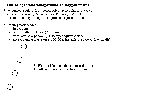
Figure 5: Spherical particles smaller than the wavelength are known to backscatter 50% of the incident light . Lateral binding forces between particles, arising from their optical interaction, tend to space them one or several wavelengths apart. This appears to favor the formation of a reflective sheet , under suitable trapping conditions.
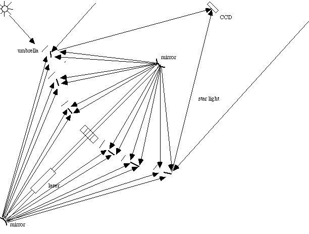
figure 6 : Distinct pellicles can be trapped by a single pair of laser beams to provide a large interferometric array having a diluted aperture. Sub-aperture phasing is directlly achieved by the trapping mechanism. The laser illumination in this case is restricted to the pellicle elements for saving laser power .